


How Precision Intermittent Motion Drives Improve Indexing Accuracy
Indexing accuracy is not created by the intermittent motion device alone. It is the result of a complete motion chain: the drive’s mechanical geometry, servo or motor control, reducer behavior, load inertia, transmission stiffness, sensing strategy, and the machine frame’s ability to resist deflection. In printing, die-cutting, folding, and carton transfer equipment, a precision intermittent motion drive improves accuracy because it converts continuous motor rotation into a controlled move–dwell cycle with repeatable angular or linear positioning.
The critical distinction is between reaching a position and settling at that position under production load. A mechanism may repeatedly arrive near its nominal index point while still producing registration variation, inconsistent die-cut locations, unstable crease-to-print relationships, or carton misalignment at the next station. Precision intermittent motion systems are designed to manage this transition from movement to dwell more predictably, but their real performance depends heavily on how the system is specified and integrated.
Why indexing accuracy matters in converting and packaging equipment
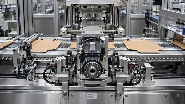
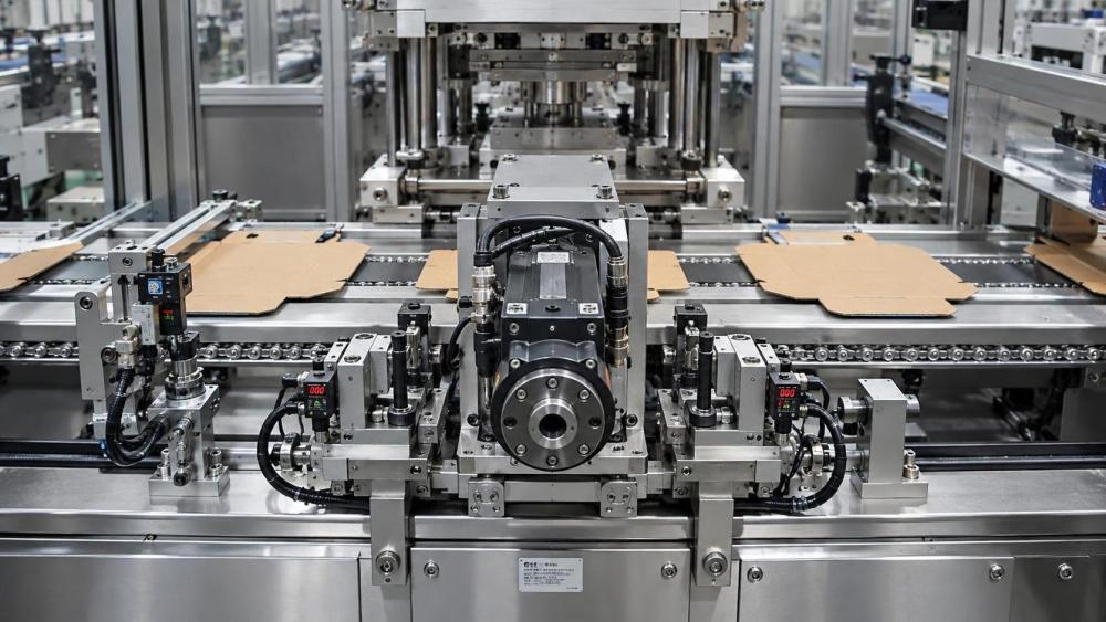
Intermittent movement is used wherever a sheet, web section, carton blank, or product must be advanced by a defined pitch and then held stationary long enough for another operation to occur. Typical examples include flatbed die-cutters, foil stamping machines, carton feeders, window patching systems, inspection stations, coding units, pick-and-place modules, and folder gluer transfer sections.
In these applications, the dwell period is not idle time. It is the operating window in which printing, cutting, embossing, gluing, inspection, coding, or transfer must occur. If the material has not fully settled when the process station begins work, the resulting error may appear as:
- print-to-die-cut misregistration;
- variation in foil stamp placement;
- inconsistent crease alignment;
- glue patterns shifted from their intended panel location;
- barcode or variable-code placement errors;
- poor transfer into downstream folding, stacking, or robotic handling equipment.
The effect is often cumulative. A small positional deviation at a feeder can become a larger visible defect after printing, cutting, folding, and gluing. For this reason, indexing performance should be evaluated as a process capability issue rather than as an isolated drive specification.
What a precision intermittent motion drive changes
A precision intermittent motion drive imposes a defined motion profile rather than relying on a loosely controlled start-stop mechanism. Depending on the machine architecture, this may be achieved through mechanical indexing units, such as cam-driven indexers, or through servo-controlled rotary and linear axes. Hybrid arrangements are also common: a mechanical intermittent mechanism may establish repeatable dwell positions, while electronic control synchronizes upstream feeding, registration correction, inspection triggers, or downstream transfer.
The value of the system lies in controlling three conditions at the same time:
- Index displacement: the commanded distance or angle of each advance;
- motion law: the acceleration, velocity, deceleration, and jerk profile used to complete the advance;
- dwell stability: the ability to hold the target position without rebound, drift, torsional wind-up, or load-induced movement.
A conventional intermittent mechanism may provide a basic move-and-stop function, but precision indexing requires more than a nominal stop position. The machine must avoid excessive impact at the end of travel, because impact excites vibration in shafts, belts, gripper bars, chains, frames, tooling, and the material itself. In a high-speed die-cutting or carton handling sequence, this vibration can continue into the dwell period and reduce the effective working time available for accurate processing.
Mechanical cam indexers are valued for deterministic motion and fixed geometry. Properly designed cam profiles can produce smooth acceleration and deceleration while maintaining a repeatable dwell. Servo indexing systems offer greater flexibility in pitch, timing, acceleration, and recipe changes. Their accuracy, however, depends on encoder resolution, feedback placement, controller tuning, drivetrain stiffness, and the ability of the motor to control the actual load rather than merely the motor shaft.
Accuracy, repeatability, and resolution are different measurements
These terms are frequently used interchangeably, yet they describe different properties and should not be accepted as equivalent during technical evaluation.
Positioning accuracy is the difference between the commanded position and the actual achieved position. If a mechanism is commanded to index 300 mm, the relevant question is how close the material or tooling arrives to the true 300 mm position under defined operating conditions.
Repeatability describes the spread of actual positions over repeated cycles. A system can be highly repeatable while consistently offset from the nominal position. For example, a feeder may stop at nearly the same incorrect position each time. This condition may be corrected through calibration or registration offset, but only if the offset remains stable.
Resolution is the smallest command increment that a controller or encoder can distinguish. High encoder resolution does not guarantee high indexing accuracy. Backlash, compliant belts, gear tooth variation, shaft torsion, bearing clearance, and structural deflection can all produce errors larger than the nominal encoder increment.
Settling time is equally important, although it is sometimes omitted from drive specifications. It is the interval required after the move for residual position error and vibration to fall within the process tolerance. A system that completes an index quickly but requires a long settling period may provide less usable dwell time than a slower but smoother motion profile.
Technical acceptance should therefore define the measurement point. Measuring the motor encoder may be adequate for evaluating the motor loop, but it does not confirm the position of the sheet, blank, gripper bar, die-cutting station, or carrier fixture. When product quality depends on the final transported object, the verification method should observe the relevant machine output point.
The motion profile determines whether speed damages precision
Higher cycle speed does not automatically reduce accuracy. The problem arises when the required index distance must be completed in less time without sufficient control of acceleration and jerk. Jerk is the rate of change of acceleration. High jerk produces abrupt force changes, which are particularly damaging in machines with flexible transmission elements or variable product loads.
A short index with a light carton blank may tolerate aggressive acceleration. The same profile applied to a heavy carrier, a vacuum transport frame, a stack of corrugated sheets, or a long gripper bar may create oscillation that continues after the axis reaches its nominal position. In sheet-fed printing and converting equipment, this can appear as intermittent registration instability rather than a constant offset.
Precision intermittent motion drives improve this condition by using a controlled acceleration path. In mechanical systems, the cam geometry determines the motion law. In servo systems, the controller can apply S-curve or other jerk-limited profiles. The correct profile is not necessarily the smoothest possible one; it is the profile that achieves the required cycle time while keeping residual vibration and following error within the process tolerance.
Changing the motion profile also changes torque demand. A profile that reduces shock may require more travel time, while a profile that shortens travel time may increase peak torque and thermal load. The evaluation should examine the full duty cycle rather than motor peak torque alone.
Load inertia and reflected inertia often decide the result
Intermittent axes are sensitive to the relationship between motor inertia and load inertia. The motor does not only accelerate the transported material. It must accelerate every rotating and translating component connected to the axis: couplings, shafts, gears, pulleys, belts, chains, drums, carrier assemblies, tooling, and sometimes vacuum or gripper mechanisms.
Where a reducer is used, load inertia is reflected back to the motor according to the square of the reduction ratio. This can improve motor-side control authority, but it does not eliminate backlash, torsional compliance, gear mesh variation, or losses within the transmission. A reducer selected only for torque multiplication may introduce positional uncertainty that becomes visible at the process station.
Load variation must also be considered. Corrugated board grade, sheet size, moisture condition, vacuum holding force, stack friction, and tooling changes can alter the effective load. In carton converting, a machine may appear stable during commissioning with one substrate and become less stable when running lighter stock, larger blanks, or products with different friction characteristics. The drive system should be assessed across the expected operating envelope, not at one favorable condition.
The weak point is often outside the drive
A high-precision indexer cannot compensate for loose chains, worn sprockets, inconsistent gripper closure, slipping belts, unstable vacuum pickup, or a flexible machine frame. These issues alter the relationship between the drive output and the actual product position.
Backlash is particularly important where motion reverses or where torque changes direction during deceleration and dwell. In a geared system, backlash may allow the load to move slightly even though the motor encoder reports a stable position. Belt-driven systems avoid gear backlash but can introduce elastic stretch and phase lag. Chain-driven systems can be robust for heavy transport duties, yet chain pitch variation, lubrication condition, tension, and sprocket wear influence positional consistency.
Couplings should not be treated as minor hardware. A torsionally soft coupling may protect components from shock but can reduce positional stiffness. A very rigid coupling may improve immediate response but transfer more vibration and alignment error into bearings and shafts. The appropriate choice depends on torque, shaft alignment, frequency response, and the allowable position error at the process point.
Structural stiffness is equally relevant. If a die-cutting platen, feeder frame, or sensor bracket deflects under dynamic load, improved drive precision may not translate into better finished-product accuracy. This is why a complete assessment includes mechanical resonance, not just nominal axis accuracy.
Feedback architecture determines what the controller can correct
Servo systems are often described as closed loop, but the loop may close only around the motor encoder. This arrangement can control motor position accurately while leaving gearbox output error, belt compliance, and load movement unobserved.
For demanding indexing tasks, feedback can be placed closer to the controlled output. An output encoder, linear scale, registration sensor, or vision-based reference can provide information about the driven element or product position. This does not mean every axis requires external feedback. Additional sensors increase cost, integration effort, wiring complexity, and diagnostic requirements. They are justified where the mechanical path between motor and process point is long, compliant, variable, or critical to quality.
Printing and converting machinery may also use registration feedback from printed marks or material edges. Such feedback corrects process-to-material alignment, which is different from correcting basic axis position. A precision intermittent motion drive establishes repeatable transport; registration control addresses variation in the incoming material, print position, stretch, slip, or previous process stage. The two functions should be coordinated rather than treated as substitutes.
How to specify an indexing requirement without creating an unusable acceptance target
Statements such as “high precision” or “±0.1 mm accuracy” are incomplete unless they define the operating conditions. A meaningful requirement identifies the index length, cycle rate, load, product condition, measurement location, number of cycles, warm-up state, and allowable error type.
For example, a requirement may distinguish among static positioning error, cycle-to-cycle repeatability, maximum dynamic following error, residual vibration during dwell, and registration error measured on the processed sheet. These values should not be assumed to be identical. A machine can meet a static axis test yet fail a production-quality requirement because vibration, material slip, or feeder variation occurs at operating speed.
Acceptance testing should also specify whether errors are measured in one direction only or include reversals, stops after emergency deceleration, recipe changes, and long-duration running. Thermal expansion, lubricant condition, servo temperature, and component settling can change behavior after the machine has operated for an extended period.
There is no single universal indexing-accuracy figure suitable for all printing and packaging applications. Tolerance must be derived from the process. Die-cutting relative to printed graphics, embossing placement, code readability, glue-panel location, and downstream folding tolerance each impose different limits. The required drive performance should be tighter than the process tolerance by an appropriate engineering margin, while recognizing that the drive is only one contributor to total variation.
Safety and control integration cannot be separated from precision
Intermittent equipment must stop and restart safely, particularly where operators access feeders, delivery sections, die stations, or material-clearance areas. Safety functions affect motion behavior: safe torque removal, controlled stopping, braking arrangements, and restart logic must be designed so they do not create unexpected mechanical movement or loss of reference position.
Machine-level risk assessment is generally addressed through frameworks such as ISO 12100, while electrical equipment design is commonly considered against IEC 60204-1 where applicable. Servo drive safety functions may be evaluated using relevant functional-safety standards, depending on the machine architecture and intended market. Compliance review should not be reduced to checking whether a drive offers a safety feature; the safety function must be integrated, validated, and documented at the machine level.
Precision also depends on controlled recovery after a stop. If an interrupted cycle requires manual repositioning, a lost encoder reference, or uncontrolled product removal, the machine needs a defined homing and re-synchronization sequence before quality production resumes. This is especially important when the intermittent axis is electronically linked to printing, cutting, inspection, or code verification stations.
What to examine before approving a precision intermittent motion solution
The most useful technical review starts with the process tolerance and works backward through the motion system. The key questions are whether the requested accuracy applies to the motor, the mechanism output, or the product; whether the dwell is long enough after settling; how the axis behaves across the actual substrate and load range; and what elements between the drive and process point can introduce compliance or slip.
A precision intermittent motion drive is most valuable when it is matched to a defined indexing duty rather than selected as an isolated high-specification component. The correct combination of motion law, mechanical stiffness, inertia matching, feedback location, registration strategy, and acceptance measurement can convert nominal positioning capability into stable production accuracy. Without that system-level discipline, a highly capable drive may simply reveal the limitations of the surrounding machine.
Related News
 What Drives the Total Cost of a Web Tension Control SystemWeb tension controller manufacturer insights: uncover total system costs, from installation and integration to waste reduction, uptime, and long-term support.Prof. Kaelen Sterling
 How Real Time Ink Viscosity Sensors Improve Flexo Press StabilityReal time ink viscosity sensors help flexo printers stabilize color, reduce waste, and control ink drift with faster, data-driven adjustments.Prof. Kaelen Sterling
 How to Compare Ink Viscosity Sensors Price Against Process ValueInk viscosity sensors price is only one factor. Learn how to compare sensor costs with quality, waste reduction, automation needs, and long-term press value.Prof. Kaelen Sterling
 Ink Handling Systems: Choosing the Right Setup for Viscosity ControlInk handling systems for flexographic printing: discover how to choose viscosity control, circulation, cleaning, and automation setups that reduce waste and improve color consistency.Prof. Kaelen Sterling
 How to Choose an Ink Recirculation System Manufacturer for Stable Print QualityChoose an ink recirculation system manufacturer that delivers stable print quality through precise flow control, ink compatibility, cleanability, and reliable automation.Prof. Kaelen Sterling
 How Precision Intermittent Motion Drives Improve Indexing AccuracyPrecision intermittent motion drive solutions improve indexing accuracy, reduce vibration, and stabilize dwell performance for high-speed packaging and converting equipment.Prof. Kaelen Sterling