


How Blanking Machines Remove Carton Waste Without Damaging Blanks
A die-cut carton sheet can leave the press looking clean, yet develop torn tabs, scuffed print, or bent panels during waste removal. These defects become especially disruptive when blanks reach the folder gluer: damaged edges can affect feeding, distorted creases can alter folding, and loose fibers can contaminate glue areas. Increasing blanking force may release a stubborn sheet, but it can also turn a separation problem into a quality problem.
Blanking Machines protect carton blanks by controlling where separation occurs and how the sheet is supported. Matched upper and lower tooling separates usable blanks from the waste skeleton while maintaining alignment and limiting unwanted bending. Damage-free operation depends on complete die-cutting, correctly designed holding nicks, suitable support, and coordinated machine motion—not force alone. When defects appear, the first task is to identify whether they originate in cutting, positioning, separation, or delivery.
The separation point: where waste releases and blanks stay intact
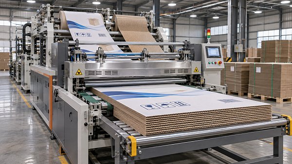
In a typical flatbed converting line, die-cutting creates the carton outlines and creases. Small holding bridges, commonly called nicks, may keep the cut sheet together during transport. A stripping station removes designated internal waste and other scrap, depending on the machine configuration. The blanking station then separates individual blanks from the remaining skeleton and delivers them into stacks or another collection arrangement.
Stripping and blanking are therefore related but different operations. Removing a window cutout does not necessarily separate the carton from its surrounding sheet. Likewise, blanking should not be expected to correct waste that the preceding stripping operation failed to remove.
Many blanking systems use an upper tool that acts on the blanks and a lower grid or receiving tool with openings matched to their geometry. The skeleton is retained or supported while the blanks move through the intended openings. Other designs use different separation and collection arrangements, so tooling and adjustment procedures must follow the specific machine documentation.
The important mechanical condition is consistent: separation loads must act at the intended cut boundaries while vulnerable panels remain adequately supported. A narrow flap should not become the load-bearing point for a large blank, and a grid edge should not catch a crease, locking tab, or printed surface.

Start with the cut sheet, not the pressure setting
A blank that remains attached may have an intentional nick, an incomplete cut, or a misaligned separation path. These conditions can look similar at the delivery end but require different corrections. Before changing the blanking settings, inspect representative sheets after die-cutting and, where practical, after stripping using approved sampling procedures.
Examine the affected outline on both faces. An intentional nick should be distinguishable from a longer uncut section. Irregular fiber tearing beyond the intended bridge may indicate inconsistent cutting, worn rule, uneven cutting pressure, or a board condition that prevents clean separation. A blanking tool cannot reliably compensate for these upstream faults without placing additional stress on the carton.
Holding nicks need a transport and release balance
Nicks keep sheets stable before blanking, but oversized or poorly positioned nicks require greater separation force. Bridges located on delicate tabs, visible display edges, or critical gluing areas can leave unacceptable tears even when the machine releases every blank.
Reducing all nicks is not a universal solution. Insufficient sheet integrity can allow blanks to shift or detach prematurely, creating registration errors and jams. Review nick width, quantity, and position with the die and tooling specialist. The aim is to retain the sheet through transport and release it at blanking without damaging functional edges.
Board condition also changes this balance. Dry, brittle material may crack around bridges; softer or moisture-affected material may stretch and pull fibers. Corrugated board adds concerns about flute crushing and liner separation. Treat a change in board grade, caliper, coating, or moisture condition as a reason to reassess the setup rather than reuse the previous settings automatically.
Match the tooling to the blank’s weak points
Correct tooling starts with the actual die layout and board specification, not merely the overall sheet dimensions. Openings must provide the clearances specified for the system while supporting the skeleton and allowing blanks to pass without catching. Excessively tight openings can snag edges; poorly supported spans can let the sheet sag or distort during separation.
Pay particular attention to long narrow panels, window surrounds, tuck flaps, and asymmetric shapes. These features may need dedicated support or a revised tooling arrangement. Any added support must remain clear of the intended blank movement and must not create a new pinch or collision point.
- Contact placement: Upper-tool contact should distribute load across appropriate areas rather than concentrate it on a fragile flap or crease.
- Surface condition: Rough edges, embedded paper dust, loose fasteners, and damaged contact materials can mark print or catch fibers.
- Tool registration: Upper tooling, lower tooling, and sheet position must agree with the die-cut layout across the entire sheet.
- Material compatibility: Support and contact arrangements suitable for folding carton board may not be appropriate for corrugated material.
A repeating defect at the same position in every sheet points toward a local tool, die, or support issue. Damage that moves between positions is more likely to involve variable feeding, sheet flatness, debris, or unstable transport. This distinction helps avoid repeated adjustments to the wrong component.
Use the defect pattern to choose the next check
Record the blank position, affected edge, defect appearance, and operating conditions before making changes. Keep acceptable and rejected samples for comparison. The following patterns provide a starting point, but they do not replace inspection of the actual tooling and machine sequence.
Do not assume every defect found after blanking was created during separation. Printed surfaces may already have handling marks, and creases may already show cracking. Comparing samples from successive process stages establishes where the damage first appears.
Commission the job through controlled adjustments
Once the cut quality and tooling are acceptable, use a documented setup sequence. Tool installation and internal inspection require the machine’s specified safe isolation procedure. Trial cycles should occur only with safeguards restored and personnel outside hazardous areas.
- Confirm the job components. Verify that the die, stripping tools, blanking tools, and layout revision belong to the same job. Check material specification and orientation.
- Establish positioning. Confirm sheet registration and tooling alignment using the manufacturer’s prescribed method. Do not compensate for a misregistered sheet by increasing load.
- Begin at the approved trial condition. Use the specified setup speed and a conservative separation setting within the machine’s operating limits. Check complete release, retained waste, and blank condition.
- Change one relevant variable. Adjust only after identifying the likely cause. Record the change so its effect can be distinguished from material or feeding variation.
- Increase speed in stages. Check whether alignment, release, and delivery remain stable as dynamic loads increase. A clean low-speed sample does not establish production-speed capability.
- Verify downstream performance. Confirm that accepted blanks feed and fold correctly, particularly where tears or deformation could affect glue joints and locking features.
Machine settings may include stroke, timing, separation load, support position, or delivery controls, depending on the design. There is no universal pressure or clearance value that protects every carton. Use machine limits, tooling requirements, and job-specific acceptance criteria rather than transferring settings between unrelated layouts.
Repeatedly increasing force to overcome incomplete release is a warning sign. Stop and recheck cut continuity, nick design, alignment, and support before accepting a higher-load setup.
Protect operators during jams, cleaning, and tool changes
Blanking areas combine moving tooling, sheet transport, waste handling, and stack movement. A jam may leave material trapped under load, while pneumatic, hydraulic, spring-loaded, or gravity-driven components can retain energy after the normal stop command.
An emergency stop or an opened guard is not, by itself, proof that internal access is safe. Follow the equipment-specific isolation and lockout procedure, address stored energy, and verify the safe state before reaching into the separation area. Use approved mechanical supports where required for raised or movable assemblies.
Never bypass an interlock to watch separation at close range or clear waste during motion. Observation should use the machine’s approved viewing provisions. Inch or setup modes do not authorize entry into a hazardous zone unless the manufacturer provides a specific safeguarded procedure for that task.
Waste accumulation can conceal interference, obstruct extraction, and increase the temptation to intervene manually. Establish accessible cleaning routines, suitable waste removal capacity, and clear responsibility for stopping the machine when buildup becomes unsafe. Suspected guard, interlock, or safety-control faults require removal from service until assessed and corrected by authorized personnel.
Release the job on blank quality, not separation alone
A completed separation cycle proves only that blanks have left the skeleton. Production approval should also cover edge condition, print appearance, panel flatness, crease integrity, and stack handling. Compare samples from different positions across the sheet and from established production speed, not just the first successful trial.
Use the carton specification to judge defects. A rough bridge remnant on a nonfunctional edge may have a different acceptance limit from damage on a glue flap, locking tab, or exposed display panel. Check for loose fibers and retained waste that could interfere with gluing or contaminate the finished pack.
Keep the approved sample, tooling revision, material details, and validated settings with the job record. When a later run develops damage, these records help distinguish a changed material condition or worn tool from a setup deviation. If a layout cannot release reliably within approved machine limits, revise the die or blanking tooling rather than normalize extra force or unsafe manual intervention.
Related News
 How to Compare Laminating Machines for Packaging ApplicationsCompare Laminating Machines for packaging by material compatibility, bond quality, production speed, and operating cost. Find the right fit for your application.Post-Press Kinematics Expert
 What to Consider When Buying a Film Window Patching MachineBuying a film window patching machine? Compare material compatibility, usable output, changeovers and total costs to make a confident investment.Post-Press Kinematics Expert
 How Brass and Magnesium Embossing Dies Compare for PackagingCompare brass and magnesium Embossing Dies for packaging. Discover how detail, durability, and total tooling costs affect your choice—and find the right fit for your next project.Post-Press Kinematics Expert
 What to Check Before Buying a Steel Chase Frame for Foil StampingBuying a steel chase frame? Discover key checks for press fit, precision, heat stability, and supplier quality to avoid costly downtime and buy with confidence.Post-Press Kinematics Expert
 How Male Female Dies Create Clean Embossed Details on PaperboardMale Female Dies create crisp embossed paperboard details. Discover how die clearance, board selection, and press alignment reduce defects and deliver consistent packaging quality.Post-Press Kinematics Expert
 Why Does a Precision Embossing Die Produce Uneven Relief on Cartons?Is your precision embossing die producing uneven carton relief? Discover how to fix alignment, pressure, and board issues to reduce waste and achieve consistent results.Post-Press Kinematics Expert