


How to Select a Precision Cam Indexer for High-Speed Automation
A precision cam indexer deserves close attention when a high-speed automation station depends on an exact sequence of move, stop, process, and move again. In carton converting, printing, coding, inspection, feeding, assembly, and end-of-line handling, a small positioning error can become a registration defect, an unreliable pick, a damaged blank, or a recurring machine stop.
The right selection is rarely determined by output speed alone. A unit that appears fast enough on a catalogue chart may still be unsuitable if the driven load has high inertia, the dwell is too short for the process, the output must absorb repeated shock, or the station needs more accuracy than the mechanical system around it can preserve. Technical evaluators should begin with the actual motion duty and process tolerance, then assess whether the indexer, gearbox, coupling, tooling, and control strategy form a stable system.
Start with the motion profile, not the number of stations
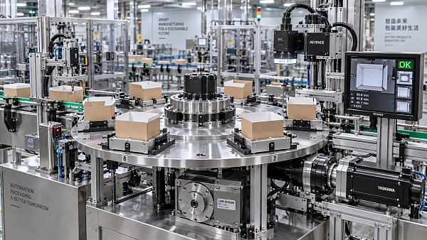
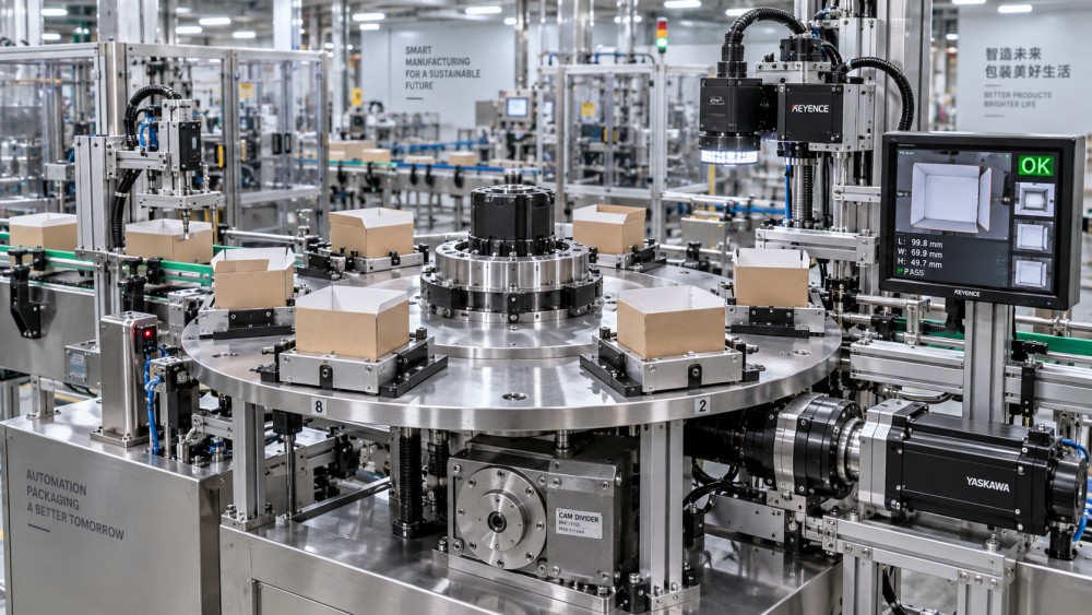
The first question is what the indexer must physically do in each cycle. A rotary cam indexer may move a dial, turret, starwheel, carton carrier, or tooling fixture through fixed angular positions. A linear unit may advance a workpiece pallet or fixture by a defined pitch. Both create repeatable intermittent motion, but their suitability depends on the full motion profile rather than simply on whether the machine needs four, six, or eight positions.
Define the cycle in operational terms:
- How many indexes occur per minute?
- What angular movement or linear pitch is required at each index?
- How much of the cycle is available for motion, and how much must remain as dwell?
- What process takes place during dwell: printing, die-cutting, gluing, inspection, filling, sealing, loading, or unloading?
- Does every cycle use the same motion, or are some positions skipped or operated differently?
Cycle rate alone can be misleading. A system running at a moderate number of cycles per minute may be mechanically demanding if the output has to complete a large movement in a very short motion window. Conversely, a machine with a high cycle rate can be manageable when the index angle is small and the dwell period is well matched to the process.
A cam indexer provides a predefined motion law. This is often an advantage where repeatability and predictable dwell are more valuable than flexible trajectories. However, the motion law must be compatible with the driven equipment. If the process station needs a long, quiet dwell for vision inspection or accurate glue application, reducing dwell merely to increase nominal throughput can undermine the function that justified the indexer in the first place.
Calculate load from inertia and operating conditions
For high-speed automation, output torque is only one part of the load assessment. The more important question is often how much inertia must be accelerated and decelerated during every index. A lightweight rotary table with a large diameter, for example, can have substantial rotational inertia. Tooling, grippers, product carriers, vacuum fixtures, and accumulated product weight may add far more inertia than the table structure itself.
Evaluators should obtain or calculate the total reflected inertia at the indexer output. This includes the driven table or conveyor mechanism, fixtures, payload, transmission components, and any motion elements connected through belts, gears, chains, or shafts. A load positioned farther from the rotation axis has a disproportionately strong effect, so a layout change can invalidate an early sizing assumption even when the total mass appears similar.
Then consider the load in its real production state. A carton feeder may run with empty carriers during commissioning but see uneven loads once product transfer begins. A palletizing fixture can have a changing center of gravity. A converting station may collect paper dust, adhesive residue, or trimmed material that affects friction and balance over time. The relevant condition is not the clean, empty machine at low speed.
A useful review separates four contributors:
- Acceleration and deceleration demand: the torque required to move the reflected inertia through the specified index time.
- External process load: force from pressing, cutting, clamping, web tension, sealing, or material handling while the mechanism is indexed or held in dwell.
- Overhung and radial loads: loads imposed on the output flange or shaft by table geometry, belt drives, sprockets, and offset tooling.
- Disturbance load: shock from part transfer, emergency stops, misfeeds, jams, or inconsistent product presentation.
Do not treat the indexer as an isolated torque source. A rigid cam mechanism can transmit disturbances efficiently. If an upstream feeder occasionally pushes a corrugated blank into a locator with excessive force, the indexer may remain within nominal running torque while the system still suffers from wear, loosening, or repeatable position drift elsewhere in the assembly.
Supplier sizing should therefore be reviewed against a documented load model, including the assumed motion time, inertia, process torque, orientation, and operating rate. A conclusion based only on motor power or the diameter of the index table is not sufficiently robust for a high-speed machine.
Positioning accuracy is a system requirement
It is easy to specify an indexer with impressive repeatability and still fail to achieve the required process accuracy at the working point. The final position of a carton, label, print image, die-cut sheet, or inspected code is affected by more than the cam mechanism. Output clearance, table stiffness, coupling torsion, fixture deflection, bearing condition, thermal movement, sensor repeatability, and the way the part is located all contribute to the final error.
For this reason, selection should begin with the process tolerance at the point of work. Ask how accurately the product or tool must arrive relative to the print cylinder, die, camera, nozzle, glue head, or robotic end effector. Work backward through the mechanical stack and allocate an acceptable error budget to each component.
A station that only transfers bundles onto a conveyor may tolerate a larger positional variation than a station that aligns folding carton blanks for foil stamping or places a code in a narrow inspection field. The indexer should be selected for the required result, not for a generic claim of “high precision.”
Repeatability and absolute accuracy should also be kept separate. A mechanism may return consistently to the same slightly offset position. That can be acceptable where the station is mechanically adjusted during setup and remains stable through a run. It is less acceptable when multiple independently timed modules must align without regular manual correction, or when job changeovers depend on stored mechanical positions.
Check how the indexer is referenced and verified. Mechanical home sensors are useful for startup and fault recovery, but they do not replace a well-designed locating arrangement. Where the process is sensitive, the output fixture should have positive datum features and a reliable method for confirming that the part is present and seated before the downstream operation begins.
Match dwell behavior to the process station
The dwell period is where the production process earns its value. During that interval, a camera captures an image, a print head deposits ink, a glue pattern is applied, a carton is erected, or a robot places a component. The indexer must hold the position with sufficient rigidity while the station applies its working forces.
Review the dwell requirement in more detail than “the table stops.” Consider whether the process needs:
- Settling time after the index before inspection or application begins;
- Resistance to vertical, radial, or tangential working force;
- Low vibration for accurate imaging, printing, or dispensing;
- A fixed mechanical relationship with another rotating or reciprocating mechanism;
- Time for pneumatic or vacuum devices to reach a stable condition.
High speed can expose a problem that is invisible during a basic demonstration. The table may reach the dwell position correctly, yet vibration from the previous move can continue long enough to affect a vision result or a fine registration operation. In that situation, increasing indexer size may help, but it may not be the primary solution. Fixture stiffness, table design, balance, coupling selection, machine base rigidity, and the mass distribution of the payload deserve the same review.
Where a process requires variable dwell or changing index angles across different jobs, evaluate whether a fixed mechanical cam indexer remains the best architecture. Servo-driven indexing can offer greater flexibility, although it introduces different concerns around tuning, torque margin, control complexity, and holding behavior. A precision cam indexer is strongest where the motion sequence is stable, repeatable, and produced at sustained speed.
Choose the mechanical arrangement that can be maintained
Cam indexers are often selected for robust, repeatable intermittent motion, but their service life depends heavily on installation quality and operating discipline. High-speed packaging and printing environments create conditions that should be considered before procurement: airborne paper dust, ink mist, adhesive contamination, washdown exposure in some lines, elevated temperatures, vibration from adjacent equipment, and frequent starts after production interruptions.
The mechanical arrangement should be examined as part of the selection. A flange-mounted rotary indexer may simplify a compact dial table. A through-shaft or hollow-shaft design may improve integration where utilities, vacuum lines, or sensors must pass through the center. A right-angle or parallel-shaft configuration can affect access, motor placement, guarding, and the ease of maintaining belts or couplings.
Service access is particularly important when the indexer sits inside a guarded converting module. Teams should establish how lubrication is checked, whether the unit requires periodic adjustment, how seals are inspected, and what must be removed to replace a motor, coupling, or output fixture. A component with an excellent duty rating can still create unnecessary downtime if routine service requires dismantling adjacent stations.
Ask suppliers for clear operating limits rather than relying on a single maximum-speed figure. Relevant questions include the allowable output inertia, permissible overhung load, duty cycle assumptions, mounting orientation, lubrication requirements, backlash characteristics, environmental protection, and the effect of repeated emergency stops. The answers should relate to the proposed configuration, not only to the broad product family.
Do not overlook transmission and motor selection
The motor, reducer, coupling, and controls determine whether the indexer receives the intended input motion. Poorly chosen transmission components can introduce torsional compliance, backlash, misalignment, or shock that compromises the output. In high-speed systems, the coupling is not a minor accessory. It must accommodate installation tolerances while remaining sufficiently torsionally stiff for the process requirement.
Motor sizing should account for starting conditions, acceleration demand, continuous thermal load, and the possibility of frequent short-cycle operation. A drive selected too close to its limit may perform adequately in a short run but overheat or become unstable over extended production. At the other extreme, excessive motor capacity without suitable control can increase shock loading during starts and stops.
For fixed-speed or repeatable high-throughput machinery, a simple motor-and-indexer arrangement may provide reliable operation. Where speed changes, synchronized modules, diagnostics, or rapid recovery after faults are required, a servo drive can add useful control capability. The decision should follow the machine architecture. Adding servo control to a fundamentally rigid sequence does not automatically improve the process, while omitting it from a system that needs coordinated electronic timing can make changeover and troubleshooting more difficult.
Validate the selection with the complete machine duty
Before release, turn the selection into a documented acceptance basis. It should state the intended product range, payload, cycle rate, index angle or pitch, dwell time, allowable positional error, external process forces, operating environment, and expected production schedule. This gives engineering, purchasing, and the supplier a common reference if performance differs after installation.
Factory testing should reproduce the meaningful duty where practical. Running an unloaded index table is useful for confirming basic motion, but it does not demonstrate stability under production inertia, working force, or an offset payload. The evaluation is stronger when the representative fixture and mass distribution are included, and when the station is observed through start-up, sustained running, normal stopping, and recovery from an interruption.
The selection decision should also leave room for reasonable operational margin. That does not mean selecting the largest possible unit. Oversizing can increase cost, space demand, and system inertia without solving a poorly defined process problem. It means avoiding a design that only works at ideal load, ideal alignment, and ideal cycle conditions.
For high-speed packaging, printing, and converting automation, a precision cam indexer is most effective when it is treated as a motion-and-process component rather than a catalogue item. Define the required dwell, model the real inertia and external loads, allocate accuracy across the whole mechanism, and confirm that maintenance access supports the production plan. Those steps produce a selection that is more likely to hold its position, its cycle time, and its value after the line moves from commissioning into daily operation.
Related News
 How to Compare Folder Gluer Systems for High-Mix Carton ProductionCompare Folder Gluer Systems for high-mix carton production with practical insights on changeovers, accuracy, glue control, integration, and lifecycle support.Post-Press Kinematics Expert
 How Mechanical Gripper Systems Improve Repeatable Material HandlingMechanical gripper system solutions improve repeatable material handling, reduce waste and downtime, and protect products across fast-paced packaging and printing lines.Post-Press Kinematics Expert
 How a Die Cutter Gripper System Improves Sheet Control and AccuracyDiscover how a die cutter gripper system improves sheet control, registration accuracy, stripping consistency, and packaging production efficiency.Post-Press Kinematics Expert
 How to Select a Precision Cam Indexer for High-Speed AutomationSelect a precision cam indexer for high-speed automation with confidence. Learn how to evaluate inertia, dwell time, accuracy, loads, and maintenance needs.Post-Press Kinematics Expert
 Why Intermittent Motion Drive System Accuracy Matters in Die CuttingIntermittent motion drive system accuracy is critical in die cutting. Learn how it improves registration, reduces waste, and boosts carton quality and line efficiency.Post-Press Kinematics Expert
 What Shapes Intermittent Motion Drive Price in Modern Carton LinesIntermittent motion drive price depends on accuracy, durability, controls, and supplier scope. Discover how carton plants compare cost, uptime, and lifecycle value before buying.Post-Press Kinematics Expert