


How Can You Prevent Die Movement in Chase Frames During Production?
How Can You Prevent Die Movement in Chase Frames During Production?
Die movement in Chase Frames can turn a stable production run into misaligned cuts, inconsistent creases, and costly downtime. Prevention starts with secure die mounting, clean contact surfaces, correctly fitted locking components, and checks for wear or damage. Just as important is following the machine manufacturer’s setup procedure rather than compensating with excessive clamping force.
For flatbed die-cutting operators, the difficult part is often identifying what actually moved. A drifting cut does not automatically mean the die slipped. Sheet registration, counterplate positioning, loose cutting rules, and movement of the entire chase assembly can produce similar symptoms. Correcting the wrong component wastes setup time and may introduce another fault.
Confirm Where the Movement Is Happening
There are three interfaces worth separating: the dieboard inside the chase, the chase inside the machine, and the sheet relative to the cutting tool. Each has different locating and retaining components. Before adjusting anything, compare the defective sheet with an approved sample and note whether the error affects the whole layout or only one area.
If the entire cutting pattern shifts relative to the print, investigate both tooling location and sheet transport. If only one rule or a small group of features moves, inspect the dieboard, rule seating, and local support. When cuts remain aligned but creases appear displaced, check the creasing counter system before blaming the chase.
A sudden offset after a jam suggests a different investigation from gradual drift as the machine reaches operating temperature. Record when the defect starts, whether it changes with speed, and whether it follows one die or one frame across different jobs. These observations narrow the search without relying on guesswork.
Stop production before checking suspected movement. Follow the machine’s isolation and lockout procedure before entering hazardous areas or handling tooling. Never reach into the cutting section, defeat an interlock, or attempt to tighten components while the machine is cycling.
Clean the Seating Surfaces, Then Check the Fit
Paper dust, dried adhesive, board fragments, and damaged packing can prevent a die from seating evenly. A lock may feel tight while pressing against contamination rather than a stable contact surface. Once that debris compresses or breaks away, the assembly can lose its original restraint.
Clean the frame’s locating faces, dieboard edges, support surfaces, and accessible locking contacts using the manufacturer-approved method. Keep oil and grease off surfaces that must remain dry for secure retention. Where a mechanism requires lubrication, apply it only at the specified points; “clean and lubricate everything” is not a sound mounting practice.
Check the actual tooling specification against the machine and chase requirements. Overall dimensions, board thickness, locating features, and mounting arrangement must match. A die that physically enters the frame is not necessarily compatible. Excessive clearance, an incorrect edge profile, or a distorted board can leave the locking system unable to locate it reliably.
Inspect the dieboard for crushed edges, delamination, cracks around fastening points, and moisture-related distortion. Store tooling under suitable conditions and support it properly during handling. Forcing a warped dieboard flat with the clamps can disguise the defect during setup without producing stable support during operation.
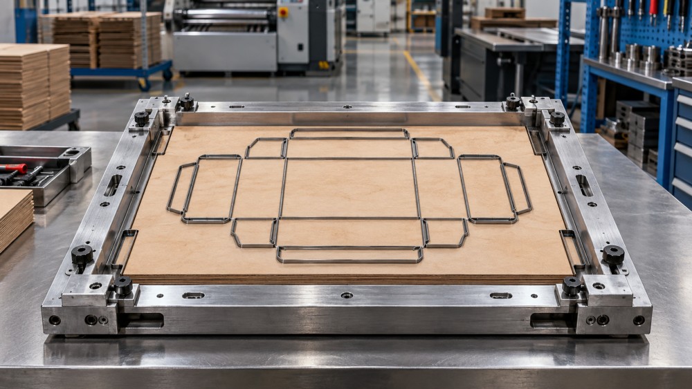
The contact path matters: the die must seat against its intended references, the locking components must engage correctly, and the chase must locate securely in the machine. A problem at any one of these interfaces can appear on the finished sheet as the same registration error.
Use the Locking System as Designed
Chase Frames do not all use the same retention method. Depending on the equipment, the arrangement may include mechanical clamps, screws, wedges, quoins, dedicated locating blocks, or powered locks. Instructions for one design should not be transferred to another simply because the components look similar.
Seat the die against the specified references before applying the prescribed locking sequence. Where several fasteners are involved, follow the manufacturer’s tightening order rather than fully tightening one corner and pulling the rest into place. Uneven loading can distort the board or leave another contact point inadequately seated.
More tightening force is not a reliable cure for slippage. Excess force can crush the dieboard, damage threads, deform contact parts, or strain the frame. Use the specified torque where one is provided, with a suitable calibrated tool. There is no universal torque value for all chase assemblies.
Examine retaining parts for rounded contact faces, damaged threads, bent components, and incomplete engagement. A screw reaching the end of its travel may feel tight without delivering the intended clamping action. Likewise, a powered lock indication should not replace the physical seating checks required by the machine’s setup procedure.
Use only approved packing, spacers, and replacement components. Loose scraps of board, improvised wedges, and unapproved adhesive tape can compress, migrate, or interfere with seating. If the die cannot be retained correctly with the specified hardware, stop and resolve the fit problem.
Check What Production Loads Are Doing to the Tool
A die that remains stable during setup but moves at production speed needs more than another tightening attempt. Cutting load, sheet release, vibration, and tooling support should be investigated together. Increasing speed may expose inadequate retention that was already present at low speed.
Review cutting pressure and makeready against the job requirements. Excessive pressure should not be used to compensate for dull rules, unsuitable cutting surfaces, incorrect rule height, or uneven support. Unnecessary loading can aggravate weaknesses in the tooling assembly, although pressure alone does not prove why a die moved.
Ejection rubber also deserves attention. Its placement, condition, and compression affect sheet release. Damaged or unsuitable rubber may allow the sheet to hang on the rules or release unevenly. Have the diemaker review persistent release problems rather than adding rubber indiscriminately or changing its specification by trial and error.
For foil stamping applications, follow the equipment’s thermal stabilization procedure and approved inspection requirements. Heat can change dimensions and loading conditions. Do not apply a generic “retighten when hot” rule: access, tooling temperature, and the locking design determine what is safe and appropriate.
Prove Stability Before Releasing the Run
A good first sheet confirms the initial setting, not its stability over time. Use the approved trial procedure, inspect representative sheets, and increase speed progressively within the machine’s operating instructions. Compare samples taken at different stages rather than judging each sheet in isolation.
A practical release check should establish:
- Cut-to-print position remains within the job’s agreed tolerance.
- Crease position and formation remain consistent across the layout.
- The sheet releases cleanly, without recurring hanging or abnormal marks.
- There are no lock warnings, unusual noises, or new vibration requiring investigation.
- Any required post-trial seating inspection has been completed with the machine safely isolated.
Set sampling frequency around the job’s risk, not a universal interval. Tight print-to-cut tolerances, unfamiliar tooling, a recently repaired chase, or a history of drift justify closer checks. After a jam, tooling adjustment, or unexplained registration change, verify stability again before returning to normal production.
Vision inspection can flag cut-to-print deviation when configured for that task, but it cannot establish whether a die is mechanically secure. Inspection detects the result; operators and maintenance personnel still need to identify the source.
When Repeated Adjustment Means Repair Is Due
A frame that needs repeated tightening during ordinary production should be treated as a fault, not an operator preference. Remove suspect components from service and have qualified personnel inspect frame condition, locating surfaces, retention hardware, and machine-side supports against the applicable service specifications.
The fault pattern helps determine the next step. If several dies drift in one chase, investigate the shared frame and its hardware. If one die causes trouble in otherwise serviceable assemblies, examine that tool’s dimensions and condition. If different chases show similar movement in the same machine, the machine-side locating system deserves attention. These are diagnostic clues, not proof; confirm compatibility before any controlled comparison.
Keep a short record linked to the die and chase identifiers: defect direction, operating conditions, findings, parts replaced, and verification result. Photographs taken during safe, isolated inspection can help maintenance staff or the tooling supplier understand the issue without repeating unsuccessful adjustments.
For Global Commercial Print & Corrugated Packaging Intelligence (CPCS), this connection between tooling condition, setup discipline, and production stability is central to evaluating converting equipment. Nominal machine speed says little about usable output if operators must repeatedly stop to recover cutting accuracy.
The next time a die appears to slip, identify which interface moved before changing pressure or tightening force. Restore the correct fit, replace defective retention parts, and verify the result under controlled production conditions. If secure mounting still cannot be confirmed, keep the tooling out of production until the cause is resolved.
Related News
 How to Choose a Sheet Feeder for Paperboard ProductionChoose the right sheet feeder for paperboard with practical tips on material handling, line speed, integration, and trials to improve production reliability.Post-Press Kinematics Expert
 How Do Creasing Dies Prevent Cracks in Folded Cartons?Creasing Dies help prevent carton fold cracks through controlled deformation. Discover key tooling factors and practical production tips for cleaner, more consistent folds.Post-Press Kinematics Expert
 How to Prevent Sheet Misfeeds in an Automatic Feeder SystemPrevent automatic feeder system misfeeds with practical checks for sheet alignment, suction, air separation, timing, and double-sheet detection.Post-Press Kinematics Expert
 How Do Non Stop Feeder Piles Reduce Die-Cutter Downtime?Discover how non stop feeder piles reduce die-cutter downtime, improve pile-change efficiency, and keep sheet feeding reliable on long production runs.Post-Press Kinematics Expert
 USITC Advances Trade Probe Into Corrugated Die-Cut BoxesCorrugated die-cut boxes face a USITC trade probe. Explore what the investigations could mean for packaging costs and sourcing.Post-Press Kinematics Expert
 What to Consider When Choosing Heavy Duty Pile TurnersChoosing heavy duty pile turners? Discover how to assess load capacity, substrate handling, safety and operating costs to find the right fit for your production line.Post-Press Kinematics Expert