


What to Evaluate When Choosing a Vision Sensor Manufacturer
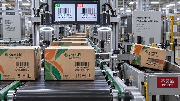
A vision sensor manufacturer should be evaluated against the inspection task, line conditions, and support burden that will remain after commissioning. A sensor that detects a simple presence condition on a stable conveyor is very different from one expected to verify variable artwork, read codes on coated board, confirm glue placement, or reject defective cartons at production speed. The comparison should begin with the real defect modes and the physical conditions in which they occur, rather than with a generic resolution or price comparison.
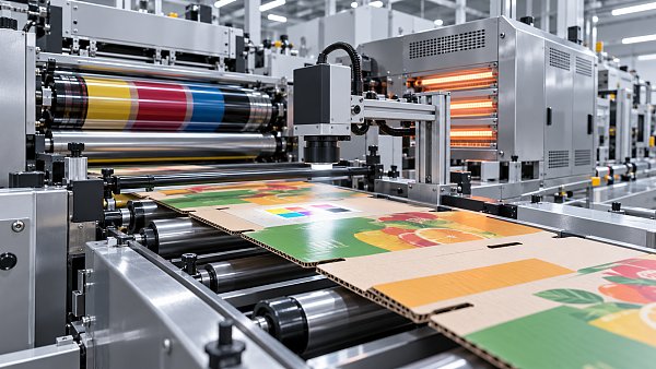
In printing, corrugated packaging, converting, and end-of-line handling, inspection failures often come from the interaction between substrate variation, lighting, motion, and application logic. A supplier that can explain those interactions clearly is usually more valuable than one that presents an impressive specification without showing how it applies to the line.
Start with the inspection decision, not the camera specification
Define exactly what the vision device must decide. “Inspect print quality” is too broad to evaluate a manufacturer. Separate the task into observable conditions: a missing date code, an unreadable barcode, a shifted label, a damaged carton flap, incorrect print registration, absent glue bead, wrong blank orientation, or a foreign object in a tray.
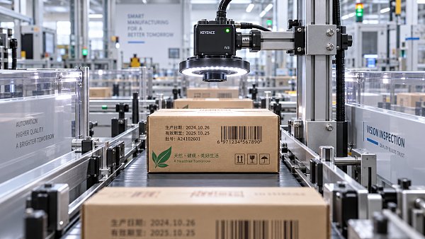
Each condition places different demands on the sensor. Presence verification may work with a small field of view and simple contrast tools. A print-registration task needs a stable reference feature and repeatable triggering. Barcode grading or data verification requires sufficient pixel density on the code itself, controlled illumination, and decoding performance that remains stable as ink density, varnish, and substrate reflectivity change. A defect that occupies only a small part of a large corrugated sheet may require either a higher-resolution system or multiple inspection zones; enlarging the field of view without considering pixel coverage can make a defect too small to classify reliably.
Ask the manufacturer to map the acceptance decision to measurable image conditions. This should include the smallest relevant feature, required positional tolerance, product presentation variation, expected surface finish, line speed, and reject timing. A demonstration that only identifies a clean reference sample does not establish that the solution will distinguish acceptable variation from a true defect.
Resolution, field of view, and working distance must be evaluated together
Resolution is often quoted as a headline number, yet it has limited meaning alone. The image must allocate enough pixels to the feature being inspected after allowing for the full field of view. A sensor viewing an entire carton blank may detect a missing large graphic but fail to verify fine type, narrow score-line alignment, or a compact 2D code. Conversely, a narrow, close-mounted view can provide strong detail but may be unsuitable when sheet position shifts across the conveyor.
Working distance changes more than image scale. It affects mounting options, vibration exposure, protection from dust, and the practical angle available for lighting. On a folder gluer or die-cutter, there may be little space between guards, transport belts, and moving assemblies. A manufacturer should be able to assess lens selection, depth of field, and mounting tolerance in the available machine envelope rather than assuming an ideal front-facing installation.
Depth of field deserves particular attention with warped corrugated board, curled sheets, carton flaps, or products carried on uneven belts. If the product surface moves beyond the usable focus range, a system may produce intermittent false rejects that resemble a software problem. The cause is optical. Test pieces should include the thickness variation, bowing, and vertical motion seen during normal production.
Lighting capability often determines inspection stability
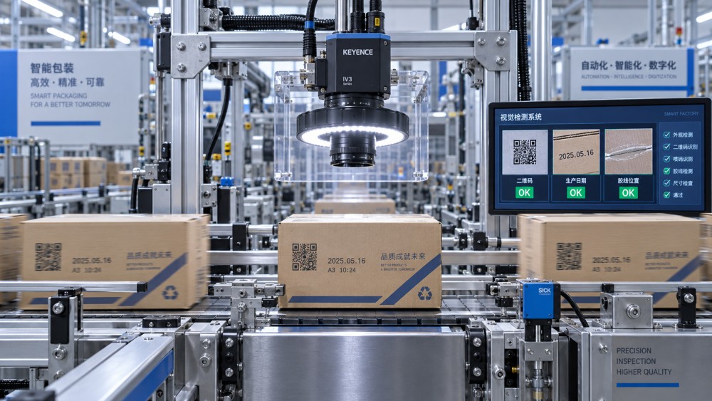
Many vision applications fail because the image changes more than the defect. Surface sheen, water-based ink variation, UV varnish, foil elements, print texture, recycled linerboard, and transparent film windows can all produce reflections or contrast changes. The right lighting method depends on what needs to be separated from the background.
Backlighting is useful where a silhouette, edge, hole, or tab position is the feature of interest. It is less useful for confirming surface print. Diffuse frontal lighting can reduce the impact of texture on uncoated board, while low-angle lighting can make raised edges, embossing, scratches, and glue patterns more visible. Polarization can reduce glare from glossy coatings, though it may also reduce useful signal from the feature being inspected. Colored lighting can improve contrast between a known ink color and its substrate, but the test must cover approved color variation and not only a single production batch.
Assess whether the manufacturer supplies lighting as an engineered part of the application or leaves the selection entirely to installation personnel. A sensor and light source that work well independently can perform poorly when their spectrum, angle, exposure settings, and enclosure geometry are not coordinated. The supplier should also state how lighting degradation, contamination, and replacement affect calibration. A high-quality initial image is not enough if an aging light or dusty protective window changes the decision threshold after weeks of production.
Speed claims need exposure, triggering, and reject timing behind them
High-speed inspection is constrained by image acquisition, processing, communication, and mechanical action. A manufacturer’s maximum frame rate does not prove that it can inspect a moving product at the required resolution. At higher web or conveyor speeds, the available exposure time becomes shorter. Insufficient illumination can then force a longer exposure, creating motion blur. More light may solve the blur, but heat, mounting space, reflective artifacts, and power requirements need consideration.
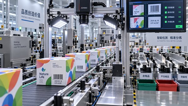
Triggering is equally important. A photoelectric trigger, encoder input, registration mark, or machine control signal must establish when the image is taken. When product spacing varies, the system needs to associate the inspection result with the correct item. On a continuous web, encoder-based position tracking is often more meaningful than a simple sensor trigger. On individually conveyed cartons, the reject output must account for belt speed changes, accumulation zones, and the physical distance to the reject device.
Request a timing diagram that traces the sequence from trigger to image capture, result generation, PLC exchange, and reject actuation. It should include the worst-case latency, not only a nominal cycle time. A fast inspection result has little value when a failed carton reaches the diverter before the reject command is valid, or when several closely spaced products make result-to-product tracking ambiguous.
Judge the inspection tools by their tolerance logic
Pattern matching, edge finding, optical character recognition, code reading, color comparison, blob analysis, and measurement tools all have useful applications. The important question is how the system behaves when normal production changes occur. Printed packaging rarely remains visually identical from run to run. Paper absorbency, ink laydown, board color, register drift, dust, and plate wear can alter the image without making the product unacceptable.
A robust application defines acceptable variability deliberately. Ask how reference images are created, how many are needed, and how pass/fail tolerances are documented. A tool trained from a single “golden sample” may be overly sensitive. At the other extreme, wide tolerances can conceal defects that the inspection was meant to catch. The manufacturer should be able to demonstrate adjustment methods that preserve traceability: who changed a threshold, which job was affected, and whether a prior approved configuration can be restored.
Where appearance-based classification is proposed, clarify the defect classes and boundary cases before purchase. A scuff, print void, shade change, and substrate blemish may look similar in a captured image but have different disposition rules. The system should not be judged solely by its ability to flag anomalies; it must support the actual accept, reject, hold, or manual-review decision required on the line.
Integration quality matters as much as image quality
A vision sensor operates within a machine, not as an isolated instrument. Examine available industrial communications, discrete I/O behavior, trigger inputs, encoder support, recipe selection, result strings, alarm handling, and connection to the line controller. The relevant protocol is the one already supported by the machine architecture and plant network, not simply the longest protocol list in a brochure.
Recipe management is especially important where short runs and frequent artwork changes are common. Confirm how a new product is selected, protected from accidental overwrite, and linked to the correct order or production code. A system that requires lengthy manual retuning between jobs may reduce the value of automated inspection. At the same time, automatic recipe selection should include safeguards against loading the wrong tolerances for a visually similar carton.
Evaluate the physical environment and serviceability
Paper dust, adhesive mist, ink aerosol, vibration, elevated temperature, and incidental impacts are common near converting and packaging equipment. The enclosure rating alone does not settle suitability. A protective window can become contaminated; cables may be exposed to repeated motion; a light mounted near a hot process can change output or require additional cooling. The proposed layout should show access for cleaning, alignment, focus adjustment, and replacement without creating an unsafe or lengthy maintenance task.
Ask what diagnostic information remains available when performance deteriorates. Useful systems show image quality, trigger status, communication state, pass/fail history, and lighting or exposure settings in a form that supports fault isolation. Without this information, a line stop can turn into a prolonged debate over whether the problem is product variation, a sensor setting, a dirty lens, a loose mount, or a PLC sequence.
Spare-part continuity also deserves a direct discussion. The relevant issue is not only whether a replacement sensor exists, but whether replacement requires a new configuration, relicensing, recalibration, firmware alignment, or changes to the control program. A manufacturer should explain the recovery procedure for a failed device and the expected method for preserving recipes and inspection records.
Use a representative acceptance trial
Bench demonstrations have value, but the final comparison should use representative materials and production conditions. Include approved samples from different runs, known defect samples, borderline print density, shifted registration, reflective finishes where applicable, and products at the largest and smallest permitted format. Present products with realistic skew, speed variation, and orientation changes. For corrugated packaging, include board grades that differ in surface texture and flatness.
Agree on the defect definitions before testing. A trial becomes misleading when one party treats every visual difference as a defect while the other expects the system to ignore approved production variation. Record the pass condition, reject condition, unresolved condition, required response time, and any cases that must be routed for review. Where live production access is unavailable, a controlled motion fixture is still preferable to hand-presented samples because it exposes timing and blur issues.
During the trial, note the effort required to create a new recipe, change inspection regions, adjust sensitivity, recover after a power interruption, and retrieve evidence for a rejected item. These tasks reveal whether the manufacturer’s software and support model fit the operating reality after installation.
Compare lifecycle support through specific commitments
Technical support should be assessed through practical questions: who owns application setup, what information is needed before installation, how remote diagnostics are performed, how escalation works during a production issue, and what training is included for configuration and maintenance. A supplier with strong optics but weak application support can leave an otherwise capable system underused.
Clarify software version policy, documentation quality, access rights, and the boundaries between sensor supplier, machine builder, controls integrator, and site maintenance staff. Inspection gaps often arise at those boundaries. For example, a camera supplier may provide a valid reject signal while the machine logic fails to track a stopped or accumulated product. Clear responsibility for commissioning tests, interface changes, and ongoing fault ownership prevents that gap from becoming a recurring production problem.
The strongest selection is supported by evidence that the proposed vision system can see the required feature, decide consistently across approved variation, stay synchronized with the line, and remain maintainable in its installed environment. Those conditions provide a more dependable basis for choosing a vision sensor manufacturer than a comparison built around sensor specifications alone.
Related News
 How to Build a Reliable Compact Vision Sensor Inspection SystemBuild a reliable compact vision sensor inspection system with proven guidance on lighting, triggering, defect detection, and production-ready quality control.Machine Vision & Coding Fellow
 How High Accuracy Spectrophotometers Improve Print Color Controlhigh accuracy spectrophotometers help print and packaging teams detect color drift early, reduce waste, improve approvals, and protect brand consistency across every production run.Machine Vision & Coding Fellow
 How Spectrophotometers for Color Matching Improve Print ConsistencySpectrophotometers for color matching help printers control Delta E, reduce waste, and deliver reliable brand color across every press run.Machine Vision & Coding Fellow
 How Print Inspection Systems Prevent Defects Before ShipmentPrint Inspection Systems help detect print, barcode, color, and coding defects in real time—improving traceability, reducing waste, and preventing costly shipment failures.Machine Vision & Coding Fellow
 Smart Cameras for Inspection That Catch Print Defects in Real TimeSmart camera for inspection solutions catch print defects in real time, verify codes, reduce false rejects, and strengthen packaging quality control.Machine Vision & Coding Fellow
 How Color Sensors Support Reliable Inline Print Quality InspectionColor Sensors enable reliable inline print quality inspection, helping packaging plants detect color drift early, reduce waste, protect brand consistency, and improve traceability.Machine Vision & Coding Fellow