


How Smart Cameras Improve Print Inspection Accuracy on Production Lines
Smart cameras improve print inspection accuracy by converting a fast-moving printed surface into a continuous stream of measured visual data. Instead of relying on periodic samples, the system compares each inspected sheet, web section, carton blank, or corrugated board area against defined tolerances while production is running. Registration movement, missing print, color drift, unreadable codes, streaks, contamination, damaged type, and repeated surface defects can be identified close to the point where they occur.
Accuracy comes from more than camera resolution. A reliable inspection result depends on the relationship between image capture, lighting, transport stability, reference data, defect logic, and response timing. A high-resolution camera installed over an unstable sheet path may produce detailed images without producing dependable decisions. Conversely, a correctly configured system with modest resolution can detect a critical missing character or barcode defect consistently when the field of view, illumination, and acceptance criteria match the application.
Inspection begins with a stable visual reference
A smart camera needs to know what an acceptable print looks like. This reference may be a master image, approved artwork region, code template, color target, or a set of feature locations such as registration marks, logos, text blocks, and die-cut edges. The reference must reflect the actual production condition, not only the original design file.
Printed substrates introduce variation that a digital artwork file does not show. Kraft linerboard, coated paper, recycled corrugated board, metallized stock, textured labels, varnished cartons, and films all reflect light differently. Ink spread on absorbent board changes fine-line appearance. Water-based ink may show different edge definition as paper moisture changes, while UV-cured areas can create glare under poorly selected lighting. The approved reference therefore needs to distinguish normal substrate texture from an actual print defect.
For repeat work, retaining the approved inspection recipe is useful only when press configuration, substrate grade, print sequence, and viewing geometry remain comparable. A recipe transferred from coated folding carton stock to uncoated corrugated linerboard can generate unnecessary rejects because the natural background pattern is different. Recipe control should include the material condition and the inspected side of the product, especially where pre-print, post-print, or reverse-side printing are involved.
Why image quality changes the inspection decision
The camera sees reflected light rather than ink intent. Illumination therefore has a direct effect on whether a defect is visible, hidden, or falsely created. Diffuse lighting is often useful for broad print coverage and uneven paper surfaces because it reduces harsh reflections. Low-angle lighting can make raised debris, wrinkles, scratches, and coating disruption more visible. Polarized arrangements may reduce glare from glossy varnish or film, but they can also reduce the contrast of features that need to be measured.
Exposure time must match line speed and product motion. If the image is blurred, thin text, barcode bars, fine rules, and registration marks can appear wider or weaker than they are. Increasing exposure can brighten a dark image, yet it also increases motion blur unless the web or sheet is effectively frozen by strobed lighting. The practical question is not whether the image looks bright on a screen. It is whether the smallest defect that matters remains separable from normal print variation at full production speed.
Lens selection matters in the same way. A wide field of view may cover an entire carton blank but reduce the number of pixels available for a small expiration code. Inspecting the full product and validating a tiny variable-data area may require separate regions of interest or more than one camera. Trying to force both tasks into one image often leads to a compromise: the overall image is useful for gross defects, while the critical code is too small for dependable verification.
Registration errors are not all the same defect
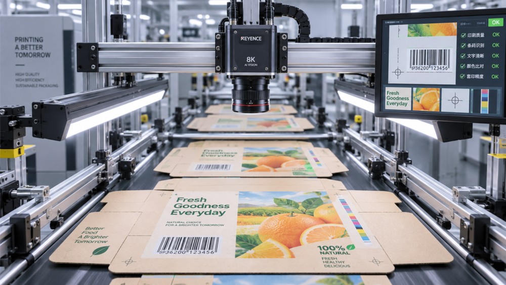
Registration inspection is frequently described as checking whether colors are aligned, but the visible fault can arise from several different movements. A uniform shift across the entire sheet points toward a positional offset between print units, sheet presentation, or image placement. A defect that grows from one side of the sheet to the other suggests skew, stretch, or angular misalignment. Variation that repeats at a fixed interval may correspond to a cylinder-related condition, plate mounting issue, or recurring transport event. A camera system can reveal these patterns when it records defect position and direction rather than only issuing a pass or fail result.
Corrugated work adds another layer of complexity. Board warp, flute profile, sheet curl, and inconsistent flatness can move the printed face away from the calibrated focal plane. The camera may interpret a change in sharpness or illumination as a positional error if the mechanical reference is not stable. Inspection mounted after a section where sheets are decelerated, transferred, or lifted needs enough mechanical control to keep the viewed surface within the optical working range.
Registration tolerance should also be related to the print feature. A slight movement in a large solid background may be visually acceptable, while the same movement around reverse text, a narrow border, a fine barcode, or a color-trapped logo can be unacceptable. Applying one broad tolerance to every printed area makes the system either insensitive to important faults or excessively prone to nuisance alarms.
Color inspection needs controlled conditions, not only a color score
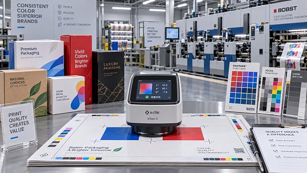
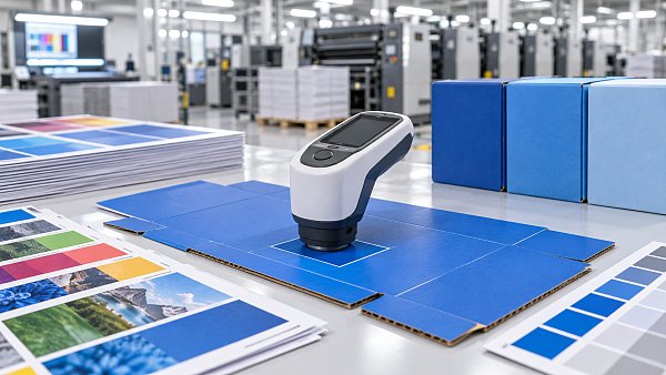
Smart cameras can detect color variation by measuring image values, comparing color patches, or evaluating changes in specified regions. These functions are valuable for identifying drift in solid areas, spot colors, overprints, and key brand elements. Their reliability depends on controlled illumination, camera calibration, stable print density, and a reference created under compatible conditions.
A lower measured contrast does not automatically indicate weak ink laydown. On corrugated board, a rougher liner surface may scatter light differently. On coated stock, gloss changes after varnishing or curing can alter the camera response even when the pigment appearance is acceptable. On flexographic work, anilox condition, plate pressure, doctor blade performance, ink viscosity, substrate absorbency, and drying can all influence the printed result. The inspection signal should therefore be connected to process observations before a color alarm is treated as proof of one particular root cause.
Color-related rules work best when they are divided by purpose. Large-area monitoring can identify gradual drift across a run. Tighter local rules can protect a logo, warning symbol, or colored code field. A single threshold for every color region tends to conceal the difference between a meaningful brand deviation and a harmless response to paper texture. Where color targets are used, their location should avoid areas affected by folds, scores, corrugated flute shadows, window patches, or variable gloss.
Variable data requires a different inspection logic
Codes, lot identifiers, date fields, serial numbers, and barcodes cannot be assessed only by comparing the entire print to a fixed master image. Some content is expected to change from unit to unit. The inspection method must establish what is variable, what format is allowed, and what data source defines the expected value.
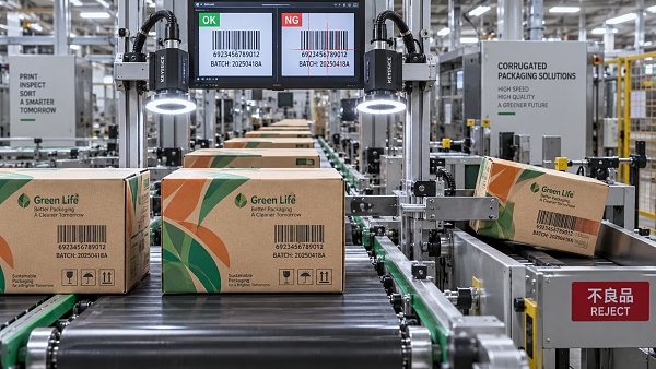
For a human-readable code, the system may verify presence, position, contrast, character pattern, and readability. For machine-readable symbols, the important question is whether the code can be decoded under defined imaging conditions, not simply whether a dark rectangle appears in the expected location. A code can be present but unreadable because bars are bridged, quiet zones are encroached upon, contrast is insufficient, ink has spread, or the symbol has been clipped by a print or die-cut shift.
False confidence often appears when presence inspection is used where content verification is required. Detecting that a code field exists does not prove that the correct batch value was printed. Conversely, a strict text comparison can reject valid production if the camera is not trained to tolerate expected font rendering, ink gain, or substrate texture. The inspection recipe needs a clear boundary between fixed artwork, variable fields, and data that must match a production record.
Defect classification makes corrective action faster
A camera that only stops a line after any failed image may prevent escape, but it offers limited process insight. Better inspection systems classify defects by type, location, recurrence, and severity. A missing print area near the lead edge has different implications from a repeating streak through a solid panel. A random spot may relate to debris, while a defect at the same image coordinate on successive sheets may indicate a damaged plate, clogged nozzle, contaminated anilox cell, or recurring mechanical mark.
Defect maps are particularly useful during long runs and frequent order changes. When failures begin immediately after a splice, plate change, wash-up, substrate change, or setup adjustment, the timing narrows the investigation. When a defect appears only at certain speeds, acceleration, web tension, impression setting, or curing condition becomes more relevant than the artwork itself.
- Random isolated defects often require review of contamination, substrate damage, dust control, ink splash, or local handling conditions.
- Periodic defects point toward rotating components, repeating plate features, cylinder surfaces, or a transport event occurring at a regular pitch.
- Progressive drift is more consistent with changes in ink condition, temperature, tension, drying, or registration control than with a fixed defect in the artwork.
- Edge-only failures deserve separate analysis because sheet skew, web wander, board warp, and lighting falloff can produce similar-looking results.
Placement on the line determines what the camera can prove
Inspection immediately after printing gives rapid feedback, but wet ink, incomplete drying, substrate flutter, and press vibration can complicate imaging. A later position may provide a flatter, more stable product and allow verification after curing, varnishing, or coding. However, placing the camera too far downstream increases the amount of material produced before a developing defect is found.
There is no universally correct inspection point. On a flexographic press, the choice may depend on whether the priority is print-unit feedback, final color appearance, or verification of a late-applied code. In a corrugated converting line, inspection before die-cutting may isolate print quality, while inspection after die-cutting can confirm the relationship between print, score, cut, and carton geometry. Where folding and gluing follow, a later inspection can reveal whether a correct flat blank becomes an incorrect finished carton due to fold alignment or glue contamination.
Transport hardware around the camera deserves as much attention as the camera itself. Guides, vacuum belts, rollers, encoder signals, triggering sensors, and product spacing affect the repeatability of each image. If the trigger is inconsistent, the same region will appear in different locations. If the encoder scaling is wrong, defect coordinates and repeat intervals become misleading. If the product surface moves vertically, focus and illumination will vary. These conditions should be resolved before inspection thresholds are tightened.
Acceptance thresholds need disciplined maintenance
Every inspection rule is a balance between escape risk and false rejection. Very loose thresholds allow meaningful defects through. Very tight thresholds can create repeated alarms from harmless texture, normal ink variation, or changing substrate reflectance. The correct tolerance is tied to the feature being protected, the process capability, and the consequence of failure.
Thresholds should not be adjusted solely to quiet alarms during a difficult run. When alarm frequency rises, the first task is to determine whether the system is revealing a genuine process change, a lighting or focus problem, an incorrect recipe, or an overly broad reference region. Reducing sensitivity without that diagnosis can mask a developing defect. Rebuilding the reference after an unapproved print condition is equally risky because the system may learn the defect as normal.
Routine verification should include lens cleanliness, lighting output, mounting rigidity, focus, trigger repeatability, image storage availability, and the condition of any protective window. Dust, dried ink mist, adhesive vapor, and board fibers can gradually reduce contrast. A camera may remain online while its effective inspection capability has deteriorated. A simple known-good and known-defect challenge image or sample provides stronger evidence than a status indicator alone.
When inspection results are linked to job identifiers, image records, rejection events, and process timestamps, the visual system becomes a traceability source rather than an isolated alarm device. The useful record is not a large archive of images with no context. It is a searchable connection between the defect, the production position, the product version, the inspected feature, and the response taken. That connection supports controlled release decisions and makes repeated faults easier to separate from one-off events.
Related News
 How to Select an Area Scan Camera for Reliable Print InspectionChoose an area scan camera for print inspection with confidence. Learn how resolution, lighting, speed, and testing affect defect detection—and make a smarter investment.Machine Vision & Coding Fellow
 How to Build a Reliable Compact Vision Sensor Inspection SystemBuild a reliable compact vision sensor inspection system with proven guidance on lighting, triggering, defect detection, and production-ready quality control.Machine Vision & Coding Fellow
 How High Accuracy Spectrophotometers Improve Print Color Controlhigh accuracy spectrophotometers help print and packaging teams detect color drift early, reduce waste, improve approvals, and protect brand consistency across every production run.Machine Vision & Coding Fellow
 How Spectrophotometers for Color Matching Improve Print ConsistencySpectrophotometers for color matching help printers control Delta E, reduce waste, and deliver reliable brand color across every press run.Machine Vision & Coding Fellow
 How Print Inspection Systems Prevent Defects Before ShipmentPrint Inspection Systems help detect print, barcode, color, and coding defects in real time—improving traceability, reducing waste, and preventing costly shipment failures.Machine Vision & Coding Fellow
 Smart Cameras for Inspection That Catch Print Defects in Real TimeSmart camera for inspection solutions catch print defects in real time, verify codes, reduce false rejects, and strengthen packaging quality control.Machine Vision & Coding Fellow