


How Line Scan Vision Systems Catch Defects Before Roll Rejection
Roll rejection is rarely caused by a defect appearing without warning. More often, a small and initially localized deviation goes undetected while material continues through a fast-moving process: a faint streak from contamination, a developing wrinkle, an unstable print density band, a missing code, or a registration shift that slowly crosses tolerance. By the time the problem is visible at the winder, stacker, or final inspection point, a large quantity of board, film, paper, or printed substrate may already be affected.
Line scan vision systems address this timing problem. Rather than inspecting occasional samples or isolated sheet images, they build a continuous digital image of a moving web or production surface, line by line. The practical value is not simply that they “see defects.” It is that they convert an emerging visual abnormality into a location, a defect classification, an alarm, and—when the line is properly integrated—a controlled production response before the defect becomes a full-roll or batch-level loss.
Why roll rejection is a detection-timing problem
In corrugated, paper converting, flexographic printing, coating, laminating, and other continuous processes, material moves much faster than an operator can inspect consistently. A defect can travel from one process section to another in seconds. If it is found only during final quality checks, the affected material may already have been printed, coated, rewound, converted, and mixed into downstream production.
This creates a different risk profile from a defect found on a discrete, slow-moving product. A defect on a web has at least four dimensions that must be understood:
- Its position: where it occurred across the width and along the machine direction.
- Its duration: whether it affected a few metres, an intermittent pattern, or an extended section of the roll.
- Its severity: whether it is cosmetic, process-related, safety-relevant, or likely to affect a functional requirement such as barcode readability or bond integrity.
- Its source: whether it originated in incoming material, printing, coating, web handling, a damaged roller, contamination, or an incorrect operating setting.
Manual inspection and periodic sampling can identify obvious failures, but they are weak at establishing duration and precise location. A line scan vision system creates a continuous inspection record, allowing the production team to determine not only that a defect occurred, but also how much material is implicated and whether it is confined to a defined section.
This distinction matters when deciding whether a roll should be rejected, downgraded, selectively removed, reworked, or released. Without reliable defect mapping, plants tend to make one of two costly decisions: discard more material than necessary because the affected length is uncertain, or release material with an unknown defect boundary.
How line scan inspection works on moving webs and sheets
A line scan camera does not capture one full rectangular image in the same way as a conventional area camera. It uses a single line of pixels, or multiple aligned sensor lines, to capture a narrow cross-web strip. As the substrate moves, an encoder synchronizes image acquisition with line speed. Thousands of adjacent scan lines are assembled into a continuous image of the material surface.
This architecture is especially suited to wide, fast-moving materials. A system can inspect the full width of corrugated liner, paper, printed web, coated stock, or other continuous substrates without relying on a snapshot large enough to cover the whole surface. Resolution depends on the camera sensor, lens selection, working distance, field of view, and the relationship between web speed and image line rate.
Lighting is equally important. The camera detects contrast, not defects in the abstract. A dark-field lighting arrangement may reveal scratches, raised contamination, wrinkles, and surface texture changes. Bright-field illumination can help identify print voids, stains, holes, and colour inconsistencies. Transmitted light can expose pinholes, tears, and thickness-related variations in materials where light can pass through. Glossy coatings, metallic inks, varnishes, and reflective surfaces often require more deliberate lighting design because glare can look like a defect or conceal one.
The inspection software compares image data against defined criteria. Depending on the application, it may identify streaks, spots, holes, edge damage, splice marks, print skips, colour deviations, misregistration, missing text, unreadable codes, contamination, wrinkles, or repeating machine-direction patterns. The system then links the event to encoder distance, cross-web position, production order, time, and, where available, relevant machine data.

The resulting output should not be treated as a collection of camera images. Its operational purpose is a defect map. That map shows where the material can be isolated, what pattern the defect followed, and whether the fault is progressing. A single visible speck may have little commercial consequence; a narrow streak repeating continuously along one side of the web points to a fundamentally different process condition.
Early warning depends on more than camera sensitivity
A common mistake is to evaluate a vision system primarily by the smallest defect it can detect. Extremely fine resolution can be useful, but it does not automatically produce better quality control. If the system detects every harmless fibre variation, coating texture change, or expected substrate feature, operators receive excessive alarms and gradually lose confidence in the inspection output.
The relevant question is whether the system can reliably distinguish defects that require action from normal material variation. That requires an inspection recipe matched to the product, substrate, print design, and quality criteria. On unprinted linerboard, a threshold for dark contamination may be appropriate. On a flexographic print job with intentional tonal variation, the same threshold could generate false calls. On coded pharmaceutical or food-related packaging, a small missing character or unreadable data element may be more significant than a larger cosmetic mark.
Effective defect detection therefore has three connected layers:
- Image quality: suitable resolution, exposure, optics, lighting, and encoder synchronization.
- Defect logic: rules or trained classification models that separate acceptable variation from defined defects.
- Response logic: a clear action tied to each meaningful event, such as marking, alarm escalation, diversion, machine adjustment, or controlled stop.
When the third layer is missing, inspection becomes passive observation. Operators may receive an alarm but have no agreed basis for deciding whether to slow the line, inspect a sample, remove material, or stop production. The result is either alarm fatigue or inconsistent decisions between shifts.
What the system can reveal before a defect spreads
Defect patterns often provide earlier evidence of process instability than a final reject decision. This is one reason continuous inspection is valuable even when the final product is still technically within tolerance.
For printing operations, a gradual colour-density change across the web can indicate ink delivery instability, anilox condition, doctor blade issues, drying imbalance, or substrate absorbency variation. Repeating defects at a regular machine-direction interval may correspond to the circumference of a roller, plate cylinder, or contaminated component. Registration drift can reveal tension instability, web stretch, servo synchronization issues, or changes in material behaviour.
In corrugated and paper-based converting, line scan vision systems can identify edge damage, crushed flutes visible through a liner surface, glue-related contamination, wrinkles, tears, adhesive streaks, surface marks, and print inconsistencies. The system does not replace process sensors for moisture, steam, tension, adhesive application, or temperature. It supplies visual confirmation of how process variation is appearing on the product. That distinction is important: vision inspection tells the team what the material looks like, while process instrumentation helps explain why it looks that way.
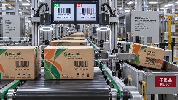
For coding and traceability applications, the inspection logic may focus on code presence, placement, contrast, character integrity, and machine-readable verification. A code can be physically present but still fail operationally if ink spread, low contrast, substrate distortion, or poor registration reduces readability. Catching that condition upstream is safer than discovering it after cartons have been packed, palletized, or released into distribution.
Defect localization changes the roll disposition decision
The strongest operational benefit of line scan vision systems is often not immediate automatic rejection. It is controlled containment. When a defect is detected and accurately logged, the production team can identify the affected web segment and prevent uncertainty from spreading through the workflow.
A practical containment sequence may include an alarm at the inspection station, a physical mark or digital reference at the web location, defect recording against the order, and communication to the rewinder, slitter, stacker, or downstream converting process. If a splice, contamination event, or print fault is limited to a known interval, that interval can be removed or evaluated separately. If the defect continues, the record helps establish the point at which a line intervention became necessary.
This is materially different from discovering a defect at the end of a roll without knowing when it began. In that case, the safe disposition decision can become unnecessarily broad because traceability is incomplete. Continuous inspection narrows the uncertainty window, but only if the position tracking remains valid through downstream handling. Encoder accuracy, roll mapping, splice management, and clear identification of parent and daughter rolls are therefore part of the quality-control system, not peripheral details.
Integration with the production line determines whether alarms are useful
A camera installation can be technically impressive and still provide limited production value if it is disconnected from line controls and quality records. Inspection data should fit the actual workflow of the plant.
At a minimum, the system needs stable speed and position information, product or job identification, and a way to retain inspection results for the relevant production run. More advanced integration can connect defect events to marking devices, automatic reject mechanisms, web guides, production execution systems, quality databases, or maintenance alerts. The appropriate level depends on the process and the consequences of a defect.
Automatic line stopping should not be treated as the default response to every fault. On a high-speed web process, unnecessary stops can create web breaks, waste, and additional safety exposure during restart. A better approach is to define escalation by defect category. A minor isolated cosmetic event may be logged for later review. A repeated defect may trigger operator verification and process adjustment. A critical issue—such as missing mandatory coding, foreign-material contamination, or a defect that compromises a specified customer requirement—may require immediate containment or stop logic.
These response rules should be established before commissioning, not improvised after the first alarm. They need to reflect product specifications, customer requirements, internal quality procedures, and the physical ability of downstream equipment to segregate affected material.
False positives and missed defects are both quality risks
Inspection performance is often discussed as though the only failure mode is a missed defect. Missed defects are serious, especially where traceability, product identification, or critical print content is involved. Yet persistent false positives can be equally damaging to the inspection program because they encourage alarm overrides and informal workarounds.
False alarms commonly arise from changing substrate appearance, variable gloss, uneven illumination, vibration, dust on optics, contaminated protective windows, incorrect exposure settings, or a recipe that does not account for approved artwork and material variation. A system set up on one paper grade may behave differently on another. A print job with large solid areas requires different detection logic from one with fine text, barcodes, or intentionally textured graphics.
Missed detections can result from insufficient optical resolution, excessive line speed for the selected camera configuration, poor contrast between defect and background, motion blur, incomplete inspection coverage, or overly broad filtering intended to reduce nuisance alarms. Neither issue is solved by software settings alone. Mechanical stability, clean optics, lighting control, web tracking, and disciplined recipe management are part of measurement reliability.
Validation should use representative defects, not only demonstration samples
System acceptance is stronger when it is based on the actual defect families that matter in production. A polished demonstration using large, high-contrast artificial marks can confirm that equipment is operational, but it does not establish whether the system will detect the subtle defects that lead to customer complaints or roll rejection.
Validation criteria should define the relevant substrate grades, web widths, operating-speed range, print designs, lighting conditions, defect sizes or severity classes, and allowable false-alarm behaviour. It should also test what happens after detection: whether the location is recorded accurately, whether marking remains aligned with the defect, whether an alarm reaches the right station, and whether the affected material can be identified after rewinding or conversion.
For safety-critical functions, the line scan system should not be assumed to replace dedicated machine safety controls. Vision inspection may support safer decisions by reducing the need for improvised manual checks near moving webs and by identifying abnormal conditions earlier. However, guards, interlocks, lockout procedures, emergency stops, and safe access arrangements remain separate obligations. A stop command generated by inspection software must also be assessed in the context of web tension, machine state, restart conditions, and the risks created by stopping the process itself.
Maintenance is part of inspection accuracy
Continuous inspection equipment is exposed to the same production environment it monitors: paper dust, ink mist, adhesive vapour, vibration, heat, and occasional web breaks. Image quality can deteriorate gradually, making degradation easy to miss until defect detection becomes unreliable.
Routine checks should cover lens and protective-window cleanliness, lighting output, camera mounting, cable condition, encoder signal integrity, cooling where fitted, and image consistency across the web width. Reference samples or controlled test marks can help verify that the inspection recipe still responds as intended. Any major change in substrate, ink, coating, speed range, or product design should trigger a review of the inspection settings rather than an assumption that the existing recipe remains valid.
The central discipline is to treat the system as a controlled measurement process. Its value comes from creating trustworthy evidence at production speed: where a defect started, how it developed, what material it affected, and whether the response prevented further nonconforming output. When that evidence is accurate and connected to containment action, line scan vision systems can turn a late, expensive roll rejection into an earlier and much more manageable production decision.
Related News
 How to Select an Area Scan Camera for Reliable Print InspectionChoose an area scan camera for print inspection with confidence. Learn how resolution, lighting, speed, and testing affect defect detection—and make a smarter investment.Machine Vision & Coding Fellow
 How to Build a Reliable Compact Vision Sensor Inspection SystemBuild a reliable compact vision sensor inspection system with proven guidance on lighting, triggering, defect detection, and production-ready quality control.Machine Vision & Coding Fellow
 How High Accuracy Spectrophotometers Improve Print Color Controlhigh accuracy spectrophotometers help print and packaging teams detect color drift early, reduce waste, improve approvals, and protect brand consistency across every production run.Machine Vision & Coding Fellow
 How Spectrophotometers for Color Matching Improve Print ConsistencySpectrophotometers for color matching help printers control Delta E, reduce waste, and deliver reliable brand color across every press run.Machine Vision & Coding Fellow
 How Print Inspection Systems Prevent Defects Before ShipmentPrint Inspection Systems help detect print, barcode, color, and coding defects in real time—improving traceability, reducing waste, and preventing costly shipment failures.Machine Vision & Coding Fellow
 Smart Cameras for Inspection That Catch Print Defects in Real TimeSmart camera for inspection solutions catch print defects in real time, verify codes, reduce false rejects, and strengthen packaging quality control.Machine Vision & Coding Fellow