


Defect Detection Systems in High-Speed Lines: What They Can and Cannot Catch
Defect Detection Systems on high-speed lines are reliable when the defect creates a measurable signal that stands out from normal process variation. They are much less reliable when the defect is subtle, transient, hidden by substrate texture, or visible only after downstream folding, gluing, or converting. In practice, the useful question is always tied to physics: can the sensor separate a bad event from acceptable noise while the web or sheet is moving at production speed?
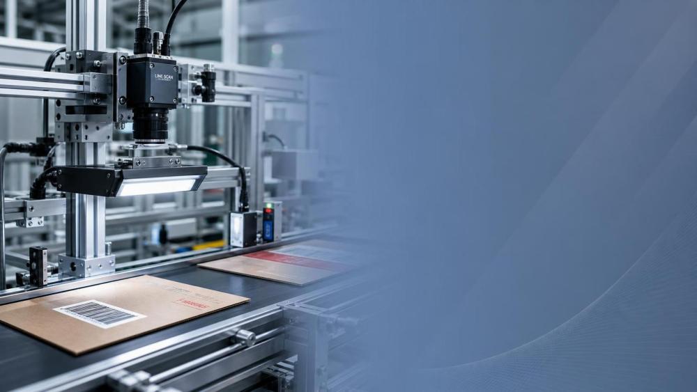
On corrugated, carton, label, and flexible packaging lines, the easiest defects to catch are usually gross print omissions, missing codes, severe registration shifts, streaks, spots, torn edges, blocked print areas, obvious splice marks, and repeatable contamination. These defects tend to create strong contrast in grayscale, color, gloss, or geometric position. A line-scan camera with stable illumination can often detect them consistently because the defect is larger than the system resolution and remains visible across multiple scans. The same is true for barcode absence, human-readable text dropout, and large hickey-type contamination in flexo or offset work, provided the optics, encoder synchronization, and trigger timing are stable.
That does not mean every visible flaw is equally detectable. A dark speck on a white coated board is easy. A faint scuff on kraft liner, a slight gloss mismatch on varnish, or a weak score crack near a printed shadow area is harder because the defect amplitude may be close to the natural variation of the substrate. Recycled liners, unbleached kraft, embossed surfaces, and rough paper all create background noise that can look like a defect to an algorithm tuned too aggressively. On glossy films, the problem shifts: specular reflection can wash out edges, and illumination geometry becomes as important as camera resolution.
Where detection usually works well
Print inspection remains the strongest use case for Defect Detection Systems. In flexographic printing, these systems can often identify missing print, plate bounce artifacts, doctor blade streaks, ink starvation bands, dirty print, splash marks, and color-to-color misregister. The reason is straightforward: these faults alter pixel intensity, edge position, or pattern consistency over a known repeat length. If the system has access to a golden reference image or a taught acceptable sample, deviation analysis is usually effective.
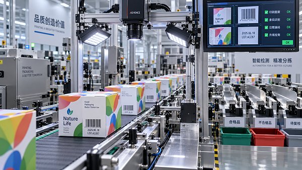
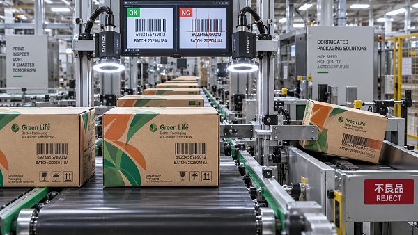
Coding and marking inspection is another strong area. Date codes, lot numbers, 1D and 2D codes, serialized strings, and OCR-readable text can be checked for presence, position, contrast, and sometimes readability grade. Inline vision does well here because the expected content area is tightly defined. Even then, the difference between “code exists” and “code is durable and scannable after abrasion, condensation, or carton folding” matters. A readable code at the camera station may still fail later if ink adhesion is weak or if the code is placed over a score line that fractures the image.
Web edge monitoring, sheet skew detection, and hole or tear detection are also relatively mature. These defects produce strong shape changes. In die-cut blanks, gross nicks, missing windows, incomplete waste stripping, or board breakout can often be detected if the inspection point is placed after the relevant operation and if the product presentation is repeatable. Folder-gluer lines can also support reliable glue pattern presence checks when ultraviolet tracer, thermal contrast, or profile-based sensing is used, though this is more dependent on adhesive type and application method than many expect.
Where the blind spots begin
Many limitations come from the gap between visual appearance and functional quality. A camera may confirm that a glue line is present, but it cannot automatically confirm bond strength. If cold glue is applied with the correct pattern but the board surface is dusty, over-varnished, or too cold, the carton may still open in transit. Hot-melt presence can be visible while wet-out remains poor. Unless destructive testing, thermal profiling, or process correlation is added, the inspection result is only partial.
The same issue appears in corrugated production. A system can detect warped board, edge damage, washboarding patterns, surface contamination, and obvious delamination if these are visible from the inspection angle. It cannot directly “see” internal flute crush, starch penetration quality, or bond integrity between liners and medium unless the defect propagates to a visible symptom. A board may look acceptable at the exit conveyor and still fail compression performance later because heat profile, moisture balance, or bonding conditions drifted upstream.
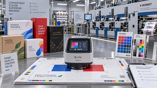
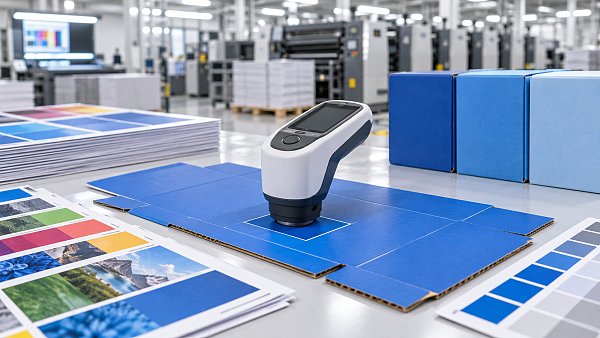
Color control is another area where expectations often exceed the sensor’s role. Vision systems can flag visible color shift, wrong artwork version, or gross density variation. They are less certain when the issue is narrow ΔE drift, metameric mismatch under different lighting, or slight hue movement within a customer tolerance band that is tighter than the line’s visual setup. If the illumination spectrum, camera calibration, and substrate whiteness are not tightly managed, the system may detect changes that are not operationally meaningful, or miss color shifts that become obvious under store lighting.
Speed changes the answer
A defect that is detectable at startup may become marginal at full production speed. At higher speeds, exposure time shortens, vibration increases, flutter becomes more pronounced, and illumination demand rises. On wide webs, small changes in web tension can shift focus across the field. On sheets, belt vibration and gripper dynamics may introduce micro-movements that smear fine detail. This is why a specification that lists camera resolution without reference to line speed, field of view, working distance, and defect size says very little about practical performance.
For example, a system tasked with catching pinholes, fine voids in solids, or hairline register movement has to maintain enough pixels on target while avoiding motion blur. If the web is running fast and the inspection width is large, there is usually a tradeoff among resolution, data rate, lighting intensity, and processing load. The result is that some defects can be seen only when the inspection zone is narrowed, when multiple cameras are tiled, or when acceptance thresholds are relaxed to keep false rejects manageable.
False positives are not a side issue here. On high-speed converting lines, an over-sensitive system can trigger unnecessary stops, eject good product, or overwhelm operators with recurring alarms tied to substrate variation rather than actual defects. Dust, paper lint, roller marks, static-related particles, board fiber tufts, and splice tape reflections can all appear as anomalies. A technically impressive system that cannot stay stable through grade changes, humidity shifts, and normal contamination will create its own waste stream.
Substrate and process effects that inspection cannot ignore
Material matters as much as sensor type. Brown corrugated board reflects differently from white SBS carton. Uncoated papers scatter light, while metallized films generate glare and local saturation. Transparent films create problems of background dependency: a wrinkle may be obvious over a dark roller and nearly invisible over a bright support. Varnish, lamination, and foil add another layer because the defect may sit in gloss, height, or texture rather than color.
In flexo, anilox wear, viscosity drift, foaming, and impression instability create patterns that can challenge simple rule-based inspection. Some are periodic and easy to learn; others evolve gradually and blend into the image until they cross a threshold too late. In die-cutting, matrix stripping issues may appear only every few cycles, especially when waste bridges weaken intermittently. In folder-gluing, fishtailing, fishmouth defects, or small panel misfolds may not be visible from a top-down camera if the carton geometry hides the fault until compression or packing.
Sensor choice therefore has to follow defect physics. Area cameras can work well for indexed products or slower intermittent motion. Line-scan cameras are often better for continuous webs and high-speed sheet surfaces because they build a continuous image with encoder-based synchronization. Thermal sensors may help with hot-melt pattern presence. 3D profiling can reveal embossed defects, raised contamination, board warp, or missing braille dots that 2D contrast imaging may miss. Ultraviolet illumination can make certain coatings or tagged adhesives stand out. None of these methods is universal, and mixed-defect environments often need more than one sensing principle.
Reference images, tolerances, and drift
Most Defect Detection Systems depend on a reference: a master image, a taught zone, a dimensional model, or a code template. This creates a quiet but important limitation. If the reference is taken during a marginal setup, the system may normalize an early defect and treat it as acceptable. If product changeovers are frequent, recipe discipline becomes part of inspection performance. Wrong reference loading, stale tolerances, or incomplete masking of variable data areas can cause persistent nuisance alarms or silent escapes.
Gradual drift is especially difficult. A sudden print dropout is easy to catch. Slow plate wear, creeping register movement, blade aging, lamp degradation, lens contamination, or buildup on transport elements may change output so slowly that adaptive algorithms absorb the shift as normal. Systems that constantly self-normalize can become blind to long-term deterioration unless a locked standard or independent calibration routine is maintained.
This is one reason acceptance windows should be tied to functional risk, not only image difference scores. A carton front panel can tolerate minor natural board variation that would look unacceptable in an algorithmic heat map. By contrast, a small defect in a barcode quiet zone or a tiny closure-glue omission may have outsized downstream impact. The inspection logic has to reflect defect location, not just defect size.
Common errors in interpreting system capability
- Presence detection is treated as proof of process integrity. It is not. Glue can be present without adequate adhesion, print can be present without rub resistance, and a die-cut can be dimensionally correct while score quality remains poor.
- Lab samples are used to judge production reliability. Controlled samples rarely reproduce dust load, vibration, warped sheets, splice events, humidity swings, or board grade variation seen in sustained runs.
- Minimum detectable defect claims are read without context. A quoted defect size only matters when paired with speed, field width, contrast condition, and acceptable false-reject rate.
- Algorithms are expected to compensate for unstable mechanics. If web guiding, encoder timing, illumination mounting, or sheet presentation is inconsistent, better software will only partially recover the signal.
There is also a persistent assumption that artificial intelligence removes the need for disciplined setup. In reality, machine learning may improve classification of complex defects or reduce manual rule tuning, but it still depends on representative training data. If the training set underrepresents substrate variation, new artwork, seasonal humidity effects, or rare intermittent faults, performance can drop sharply when production conditions move outside the learned range.
What a realistic catch envelope looks like
A realistic view of Defect Detection Systems is narrower and more useful than a broad promise of zero-defect output. They can usually catch visible, repeatable, sufficiently contrasted defects when product presentation is stable and when the inspection point is placed after the defect is created. They struggle with hidden structural failures, bond strength, subtle appearance changes near the natural variability of the substrate, and defects that emerge only after downstream handling.
That is why inspection should be read alongside process signals. Viscosity, temperature, tension, encoder health, glue pressure, vacuum stability, printhead status, and reject confirmation often explain the defect before the image does. When image inspection and machine-state data are separated, root-cause analysis becomes slower and false confidence grows. A system may accurately report what passed in front of the camera while missing the process drift that will produce the next wave of marginal product.
In high-speed lines, the strongest installations are usually the ones that admit limits clearly. They define which defects are detectable at rated speed, which ones need reduced speed or alternate lighting, which ones require off-line validation, and which ones remain process-control questions rather than inspection questions. That boundary is where technical evaluation becomes meaningful, because the value of defect detection is not in claiming total visibility, but in knowing exactly where visibility ends.
Related News
 How to Build a Reliable Compact Vision Sensor Inspection SystemBuild a reliable compact vision sensor inspection system with proven guidance on lighting, triggering, defect detection, and production-ready quality control.Machine Vision & Coding Fellow
 How High Accuracy Spectrophotometers Improve Print Color Controlhigh accuracy spectrophotometers help print and packaging teams detect color drift early, reduce waste, improve approvals, and protect brand consistency across every production run.Machine Vision & Coding Fellow
 How Spectrophotometers for Color Matching Improve Print ConsistencySpectrophotometers for color matching help printers control Delta E, reduce waste, and deliver reliable brand color across every press run.Machine Vision & Coding Fellow
 How Print Inspection Systems Prevent Defects Before ShipmentPrint Inspection Systems help detect print, barcode, color, and coding defects in real time—improving traceability, reducing waste, and preventing costly shipment failures.Machine Vision & Coding Fellow
 Smart Cameras for Inspection That Catch Print Defects in Real TimeSmart camera for inspection solutions catch print defects in real time, verify codes, reduce false rejects, and strengthen packaging quality control.Machine Vision & Coding Fellow
 How Color Sensors Support Reliable Inline Print Quality InspectionColor Sensors enable reliable inline print quality inspection, helping packaging plants detect color drift early, reduce waste, protect brand consistency, and improve traceability.Machine Vision & Coding Fellow